KrabzCAM is a web application that lets you generate G-code for various types of machining operations, such as cutting, pocketing, drilling, engraving, etc.
With KrabzCAM, you can use a design in vector graphics format (SVG or DXF) and easily create G-code for processing on a CNC machine. This manual will help you get started using KrabzCAM.
User interface
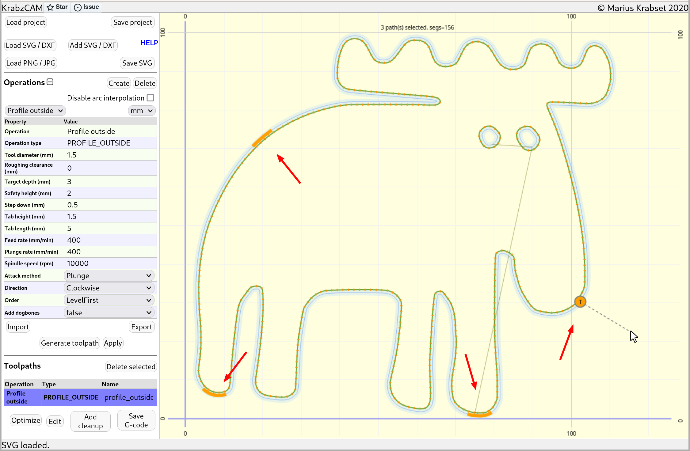
The user interface is divided into two panels; a tool panel on the left, and a 2D view on the right.
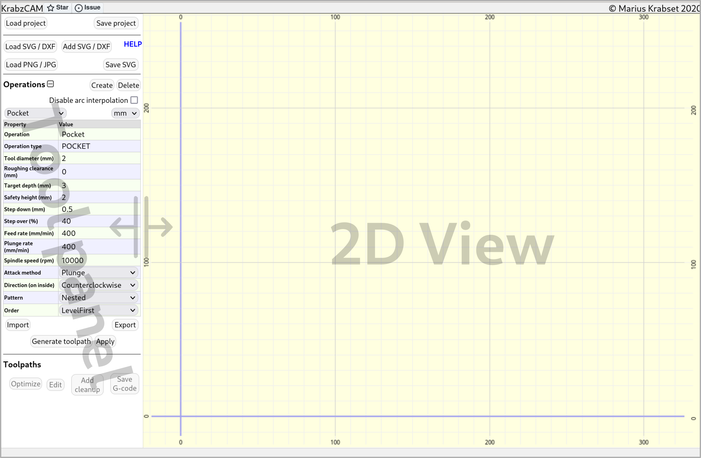
The tool panel
The tool panel contains widgets for performing most actions in KrabzCAM.
The following is a summary of these actions:
-
Load/save project
-
Set global settings
-
Load/add vector graphics (SVG or DXF)
-
Save selected vector graphics as SVG (Save SVG button)
-
Load pixel graphics (PNG / JPG)
-
Create/delete/select Operation
-
Set operation properties
-
Load/save operations (Import/Export buttons)
-
Save default operations to browser local storage
-
Reset to 'factory' operation settings.
-
Generate Toolpath for selected graphics element and selected operation
-
Select toolpath
-
Edit toolpath properties
-
Optimize toolpath (reduce amount of travel)
-
Create 'cleanup toolpath' for toolpath
-
Save toolpath(s) as g-code
The 2D view
The 2D view shows the loaded graphics, and will also a representation of the selected toolpath. The view can be panned by holding the left button while dragging the mouse, and the mouse wheel is used for zooming in and out.
When mouse pointer is in 2D view, a number of hotkeys may be used to manipulate the graphics.
These hotkeys are displayed in the background. Use h-key to toggle this display on/off.
The following is a summary of supported functionality in the 2D view:
-
Select/unselect graphical elements
-
Invert selection
-
Select all/nothing
-
Select by color
-
Move/Rotate/Scale selected graphics
-
Duplicate selected graphics
-
Delete selected graphics
-
Add simple shapes (circles, polylines and n-gons)
-
Place/remove pivot point (for scaling and rotating)
-
Add tabs to profile toolpath
-
Toggle some display settings
Typical workflow
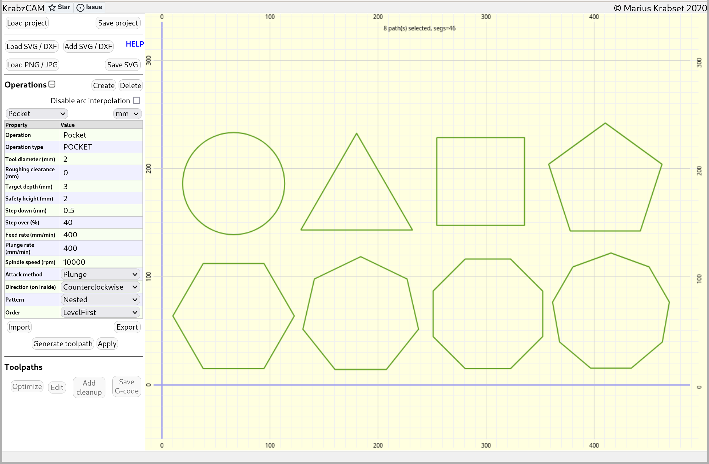
Loading/adding artwork
To get started, the first thing you’ll need to do is load your artwork. This is done by using the "Load SVG/DXF" button in the tool panel.
If you need to load from multiple files, use the "Add SVG/DXF" button instead. This will add the content without removing what’s already loaded.
|
Tip
|
KrabzCAM use 96dpi pixel resolution by default for SVG files.
Another commonly used pixel resolution is 72dpi.
You can change the SVG px resolution for import by pressing the Settings-button in the top-right corner of the tool panel.
|
If you don’t have any files and only want to work with simple shapes, you can use hotkeys in the 2D view:
-
Press
0to create a circle -
Press
2to create a polyline. Add points with mouse button and finish withEnter. -
Press
3to9to create n-gon (3 for triangle, 4 for square, etc…)
Editing the artwork
All artwork adjustments are done in the 2D view. To adjust something, you first need to select it. Selected elements are displayed in green.
Selecting
Press b for 'box-select'. The box-select operation will by default toggle between selected/unselected
, so that if something is already selected, it will be unselected, and vice versa.
Holding down SHIFT-key while box-selecting will enforce 'select-only'.
Holding down CTRL-key will enforce 'unselect-only'.
Press c for 'circle-select'. The circle-select operation will by default select everything you touch with
the circle. If you hold down CTRL, it will instead unselect everything that is touched.
Use mouse-wheel to adjust size of the selection-circle.
Press a to toggle between 'selecting all' and 'selecting nothing'.
Press i to invert the selection.
Press SHIFT-a to 'select next by color'.
If your SVG elements have different colors, this hotkey lets you cycle through each color, and
select only the elements having that color.
Moving
Press g (grab!) to move the selected elements around.
For fine-adjustments, hold Shift-key while moving.
If you only want to move horizontally or vertically, you can lock either axis by hitting x or y.
Press z to zero position of selected elements, e.g.. move to origin, or to pivot position (see below) if set.
Scaling
Press s to scale the selected elements.
Hold SHIFT for fine-adjustment.
Hold CTRL for discrete scaling steps.
Use x or y to lock axis.
(See below for use of pivot)
Individual-scaling
Press CTRL-S to scale selected paths relative to their individual center-points.
Hold SHIFT for fine-adjustment.
Normal-scaling
Press SHIFT-S to scale selected paths in normal direction.
Hold SHIFT for fine-adjustment.
Rotating
Press r to rotate the selected elements.
Hold SHIFT for fine-adjustment.
Hold CTRL for discrete increments (5 degrees).
(See below for use of pivot)
Use of pivot
Scaling and rotation is by default done relative to a calculated center-point in the middle of the selected elements. This behaviour can be overridden by setting a pivot point. When a pivot point is set, all rotations will revolve around this point, and all scaling will scale out from, or in towards this point.
Press p to set/delete a pivot point.
If a pivot already is set, pressing p will remove it.
If the pivot is not set then:
-
Pressing
pwill let you place the pivot using the left mouse button. -
Pressing
pand thenowill place the pivot at the origin.
Typing exact values
Keyboard can be used for typing exact values during scaling, rotation and single axis move operations.
Make sure mouse pointer is inside the 2d view area while typing the number, and complete operation with Enter or left mouse button.
Toggle negative/positive value with --key.
Aborting operations
Scaling, rotation and move operations can be aborted by hitting ESC.
Duplication
Hotkey d duplicates the selected elements, and initiates a move-operation so that the copy can be placed
at desired location.
|
Tip
|
It is not a good idea to leave the duplicates at the same location as the originals, since you may later not be able to separate them if they are on top of each other. |
Editing paths
While KrabzCAM is not intended to be a vector graphics editor, some very basic editing is supported. This can be useful for fixing minor issues, like cleaning up self-crossing paths and doing last minute fixes.
Hotkey TAB toggles path edit mode. When in path-editmode, the background color changes to light-blue,
and the vertices of the selected elements are displayed. These vertices can be either path segment endpoints,
or bezier control points.
In either case, the vertices can be selected individually (box-select, circle-select etc). The selected vertices can then be moved, scaled and rotated using the hotkeys described above.
Configuring an Operation
KrabzCAM offers many kinds of machining operations. Depending on the task at hand, an appropriate operation can be selected from the drop-down in the tool-panel. The operation properties then needs to be configured correctly.
We will go into detail on each operation type later.
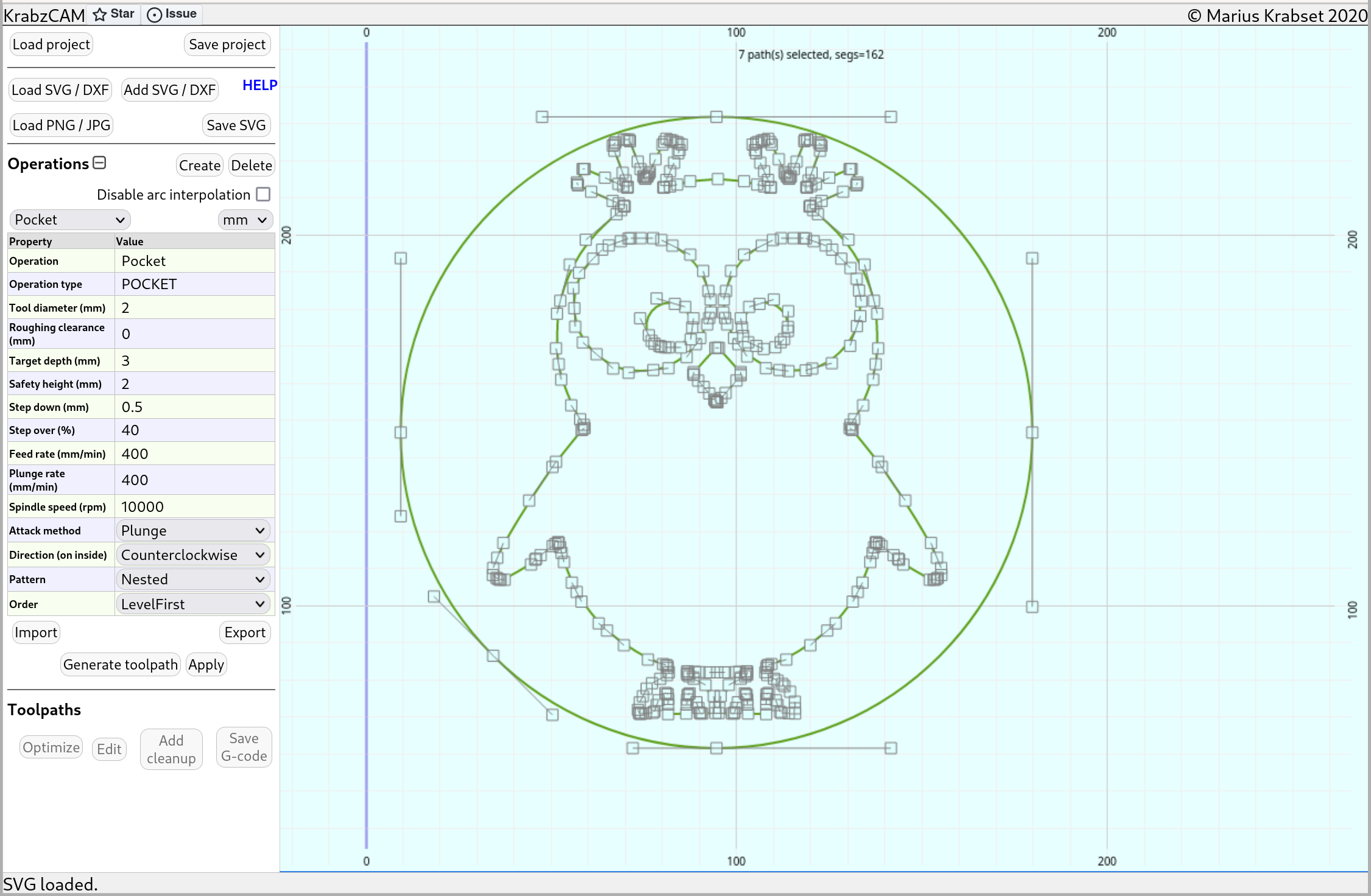
Generating a Toolpath
In KrabzCAM a Toolpath is basically an Operation applied to some elements in the 2D view.
After selecting some elements in the 2D view, and selecting/configuring an operation,
the Toolpath is created by pressing the Generate toolpath-button.
The new toolpath will show up in the toolpath-list, and it will be visualized in the 2D view.
|
Tip
|
Many operations support toolpath-optimization.
Before saving G-code, the Optimize-button will reduce processing time by reducing the amount of travel.
You may get more improvements by hitting Optimize multiple times.
|
Saving gcode
When toolpath is created, its g-code can be saved using the Save G-code-button.
If more than one toolpath is available, its also possible to join multiple toolpaths into one single g-code file.
(Typically, this can make sense if no tool-change is required)
There are also some settings for including comments, and for enforcing uppercase g-code.
Operation types
KrabzCAM can produce g-code for many kinds of operations. In this section we will go into details on each one.
Some definitions
-
An operation type is a type of operation, identified by an uppercase label. The operation types in KrabzCAM are:
-
PROFILE_INSIDE, for cutting inside profiles with milling tool.
-
PROFILE_OUTSIDE, for cutting outside profiles with milling tool.
-
POCKET, for milling out cavities with milling tool.
-
FOLLOW_PATH, for following path at center with milling tool. Typically, for engraving.
-
DRILL, for drilling operations
-
FOLLOW_PATH_LASER, for following path at center with laser tool.
-
LASERRASTER, for engraving bitmap images with laser tool.
-
RELIEF_ROUGH, for relief roughing operations before using RELIEF_FOLLOW.
-
RELIEF_FOLLOW, for creating reliefs by following a height-map using a milling tool.
-
DRAGKNIFE, for cutting soft material sheets using a drag-knife tool.
-
VPOCKET, for cutting detailed pockets using a v-bit.
-
VINLAY, for creating inlays to fit inside v-pockets.
-
HALFTONE, for creating halftone images using a v-bit.
-
STIPPLE, for creating stipple images using a laser or drill tool.
-
-
An operation is a named instance of an operation type. By default, KrabzCAM is set up with one operation pr operation type. The operations are listed in the operation dropdown in the tool panel. For instance, there is an operation named "Pocket" with the operation type POCKET. It is possible to create your own custom operations using the
Create-button in the tool panel. Custom operations can also be stored on file for later use, using theImport/Exportbuttons. -
The operation-properties are a list of configurable values for an operation. Default-values are provided by the operation type.
-
A toolpath is an operation applied to some graphic elements in the 2D view. When a toolpath is created, it gets its own copy of the operation-properties, so that it will not be affected by later changes in these properties. A toolpath generates a g-code output.
|
Tip
|
It is also possible to store your own preferred operation settings to browser local storage
using the Set as default-button. KrabzCAM will then be initialized with these settings next time you use it.
If you want to go back to using the 'factory'-settings, you can press the Reset-button to load these settings.
|
Profile inside / outside
For profiling operations the operation types are PROFILE_INSIDE and PROFILE_OUTSIDE, depending on which part to keep, the piece with the hole, or the piece leaving the hole.
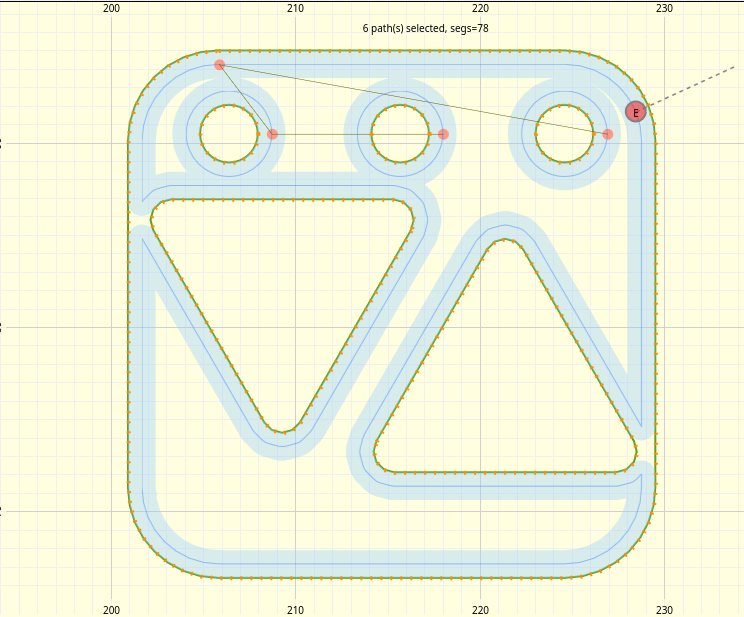
The graphical elements needs to be closed paths to be used for these operations. Open paths, e.g.. paths not forming closed loops, will be ignored. Path-elements with self intersections are also not allowed.
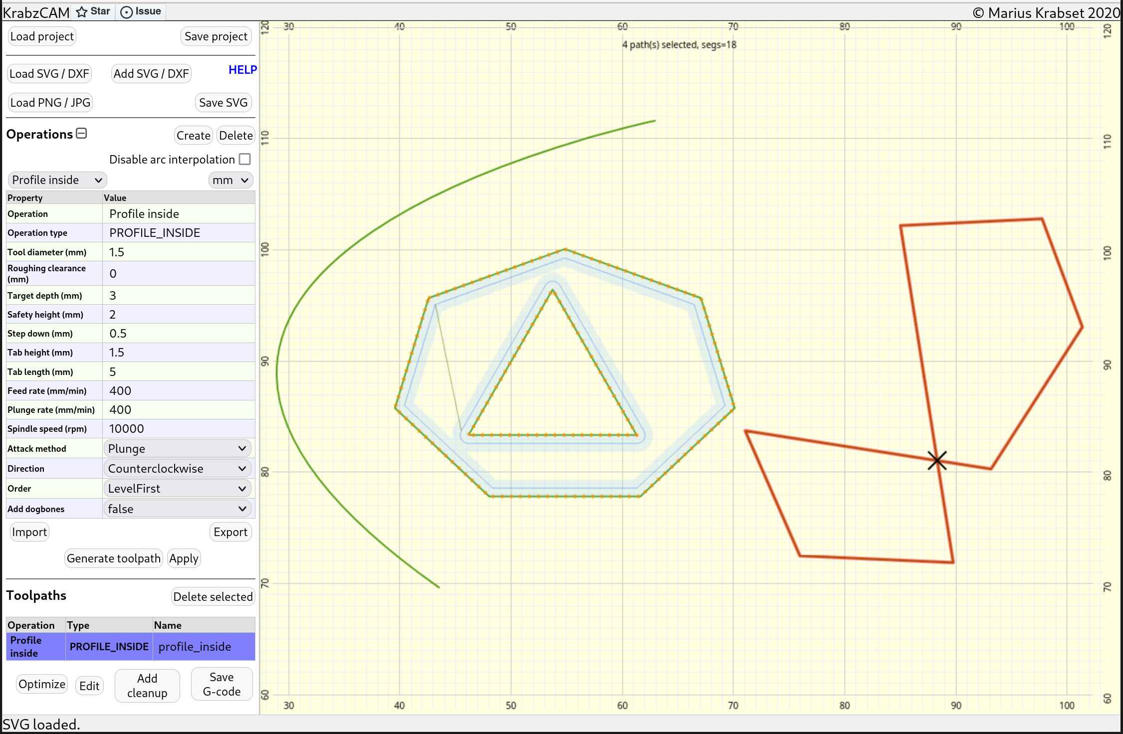
In the example above, we have tried to create an inside profile for 4 graphical elements. The resulting tool path is visualized in light blue. As we can see, the arc on the left is ignored because its open. The heptagon and triangle in the middle shows tool-paths, so these are ok. The 8-shaped closed path on the right is ignored and marked red because it intersects itself. The cross-point is marked with an 'X'.
Also notice that the triangle is cut on the outside, even though this is an inside profile operation. This is because it is contained within the heptagon. When paths are nested like this, the "odd/even-ness" of the nesting level determines if cutting is done on the inside or outside. This behaviour is common for both profiles and pockets.
Using tabs
To avoid parts coming loose when doing profiling operations, tabs can be added. A tab will leave some material behind so that the parts will be held together. The tabs can be removed later using a manual cutting tool.
Use hotkey t to enter "tab-mode". In tab mode, you can add a tab by pressing mouse button.
Added tabs are visualized in orange color.
If you hold down shift, you can select and remove existing tabs.
Changing entrypoints
Sometimes you may want to move the "entry point" of a profile cut, e.g.. the point where the cutting starts. Tool entry will often leave some marks, so it is good to move the entry point to place where these marks are not so visible.
Entry points for profiles are marked with a red dot. When a profile toolpath is chosen, press e to move the entry point
for the cut closest to the mouse pointer.
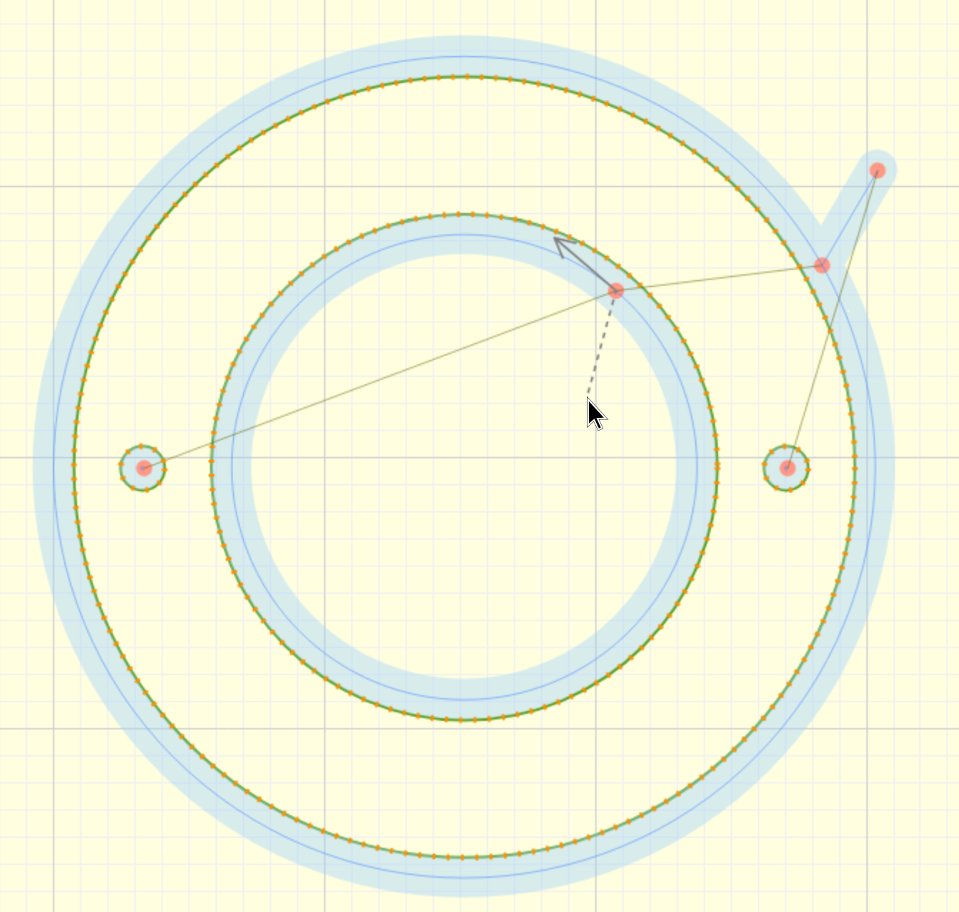
Extended entrypoints
In addition to placing the entry point on the path of a profile, the entrypoint can also be extended away from the original tool path.
This can be useful if you want the tool to enter the material somewhere away from the part you want to keep.
After placing the on-path entrypoint (using e), you can use Shift-e to create an extended entrypoint.
While placing an extended entrypoint an arrow will indicate the direction of travel along the path.
Properties:
-
Tool diameter: Diameter of the milling tool. Determines the toolpath offset.
-
Roughing clearance: Adds extra distance to the toolpath offset. Can be used for roughing passes.
-
Target depth: Determines depth of cut, relative to z-origin. Given as a positive number.
-
Safety height: Determines the z-value during travel. Choose a value high enough to avoid touching the workpiece.
-
Step down: How much z-distance to advance for each pass. If targetDepth=3 and stepDown=1, you get 3 passes.
-
Tab-height: Determines thickness of tabs. If targetDepth=3 and tabHeight=1, max cutting depth on tabs will be at z=-2.
-
Tab-lenght: Determines the width of the tabs.
-
Feed-rate: Determines speed in x/y direction during cutting.
-
Plunge-rate: Determines speed in z-direction during descent into workpiece.
-
Spindle-speed: Determines spindle speed.
-
Attack-method: Determines how to enter new depth. Use "Plunge" to dive directly down, or "Ramp" to dive diagonally.
-
Direction: Determines which way to traverse the paths, climb or conventional (clockwise/counterclockwise).
-
Order: Determines processing order. "Level First" will finish one depth for all elements first, before entering next pass. "Depth first" will go all the way down for each element before processing the next.
-
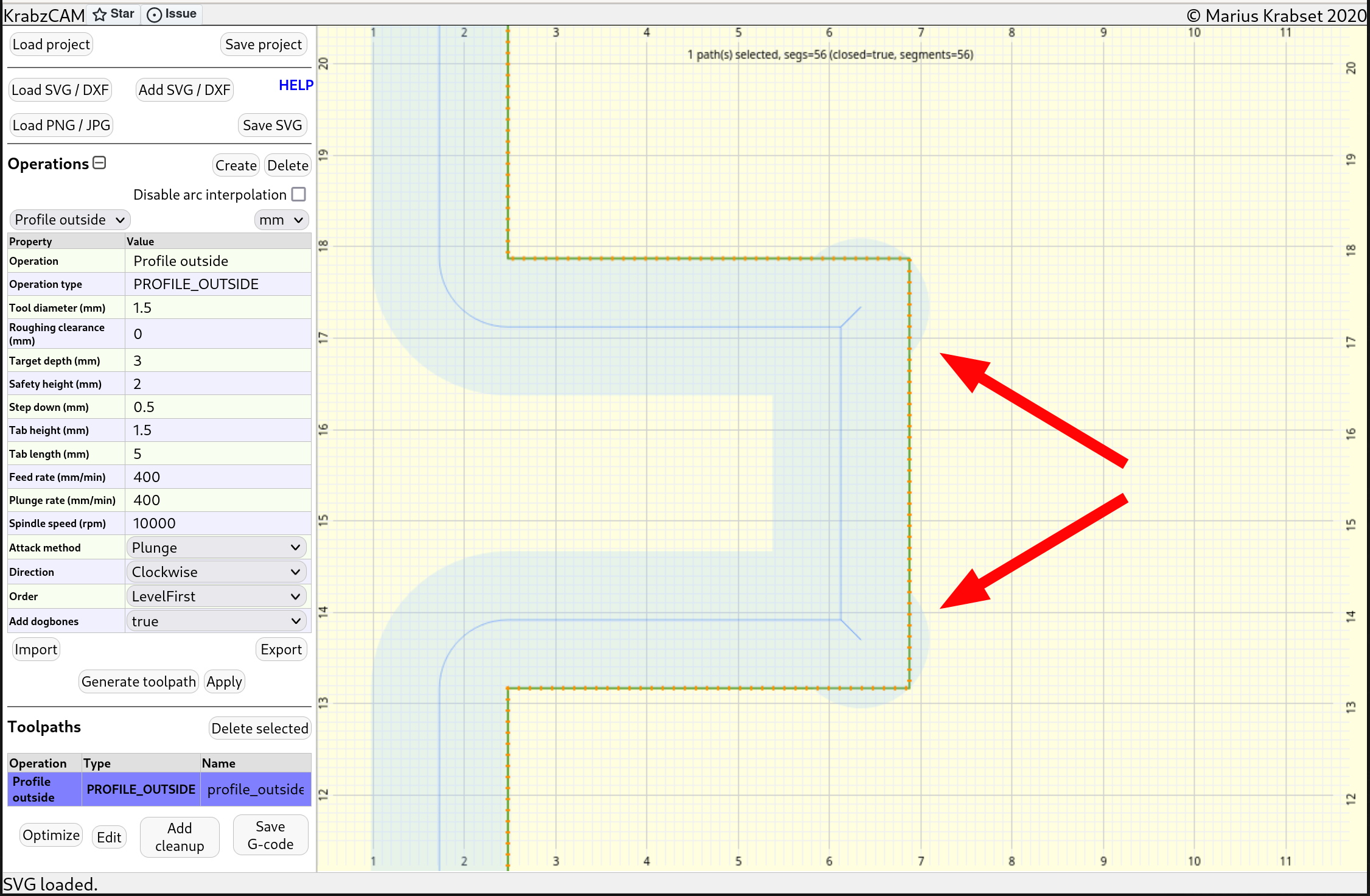
Add dogbones: Adds "dog bones" to sharp inside corners.
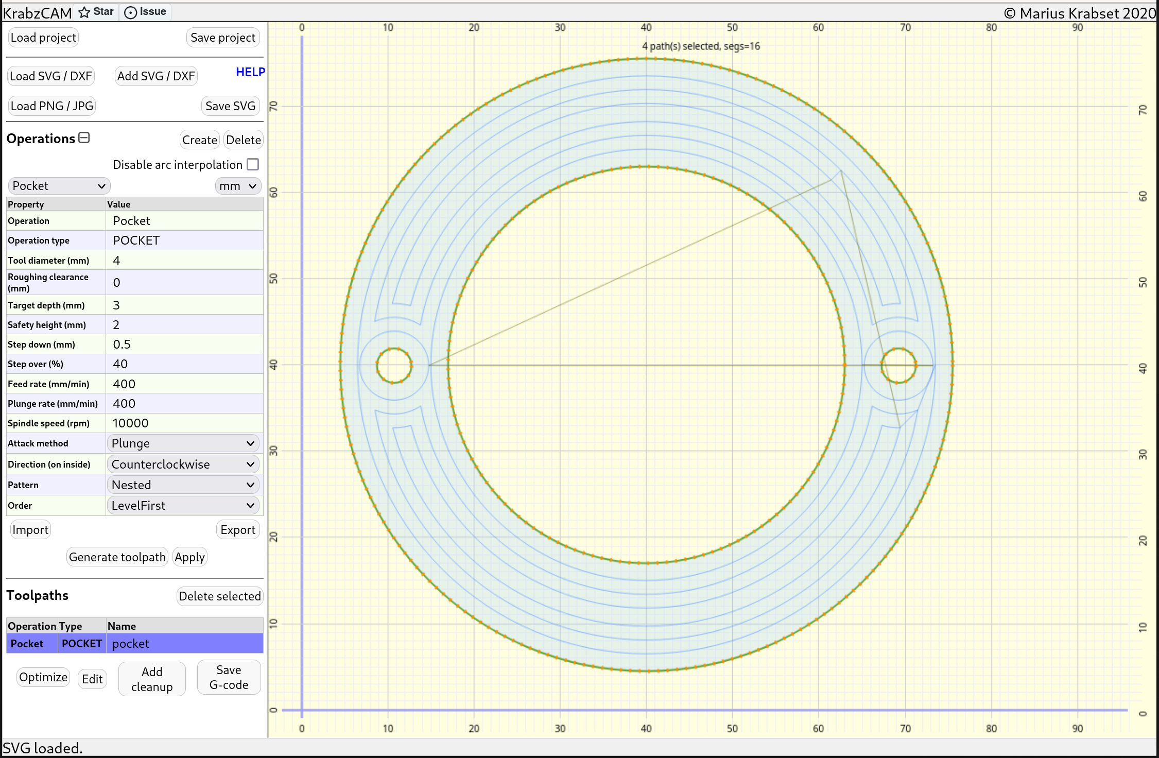
The operation type POCKET is used for creating pocketing tool paths. This operation type has lots in common with the above profiling operations. The main differences is that this operation removes a certain volume instead of just cutting out shapes. Usually, a pocketing operation does not cut all the way through the workpiece, so tabs are also not relevant.
Properties:
-
Tool diameter: Diameter of the milling tool. Determines the toolpath offset.
-
Roughing clearance: Adds extra distance to the toolpath offset. Can be used for roughing passes.
-
Target depth: Determines depth of cut, relative to z-origin. Given as a positive number.
-
Safety height: Determines the z-value during travel. Choose a value high enough to avoid touching the workpiece.
-
Step down: How much z-distance to advance for each pass. If targetDepth=3 and stepDown=1, you get 3 passes.
-
Step over: A percentage value determining how much the generated paths will overlap. 40% usually seems to be a good number.
-
Feed-rate: Determines speed in x/y direction during cutting.
-
Plunge-rate: Determines speed in z-direction during descent into workpiece.
-
Spindle-speed: Determines spindle speed.
-
Attack-method: Determines how to enter new depth. Use "Plunge" to dive directly down, or "Ramp" to dive diagonally.
-
Direction: Determines which way to traverse the paths, climb (counterclockwise) or conventional (clockwise).
-
Pattern: Determines tool path pattern.
-
Nested creates loops nested inside each other (see image above)
-
Line create a pattern with straight lines. Discussed here.
-
-
LineAngle: Determines line-angle for "Line" pattern. A value of zero will make horizontal lines. 90 will give vertical lines.
-
LineDirection: For line-pattern, you can choose between going back-and-forth in a zigzag manner, or doing all strokes in the same direction.
-
LayerDirection: For nested-pattern, you can choose between going through the layers in Inward or Outward direction.
-
Order: Determines processing order.
-
Level First will finish one depth for all elements first, before entering next pass.
-
Depth first will go all the way down for each element before processing the next.
-
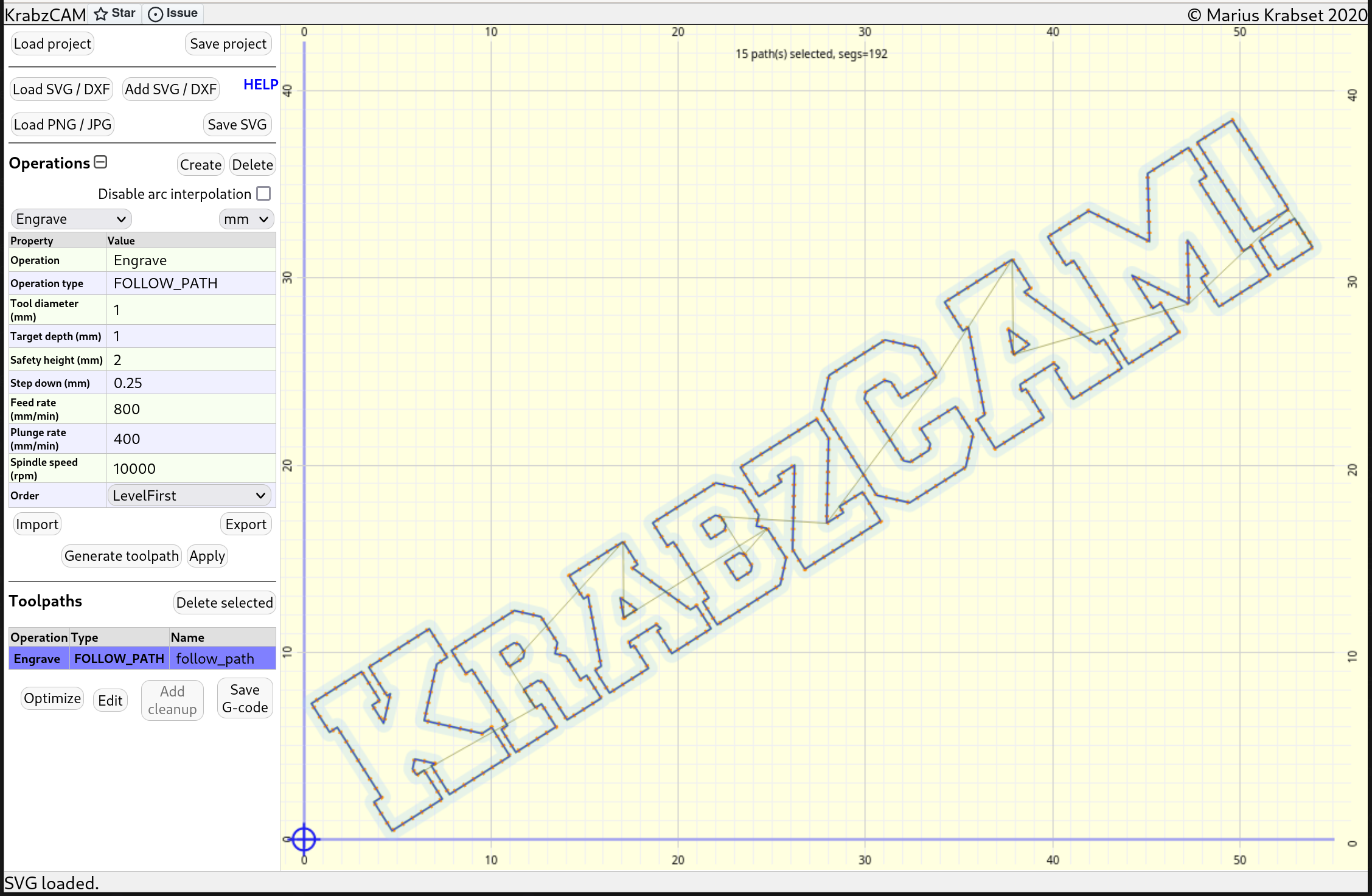
Engrave
The operation type FOLLOW_PATH is mostly used for engraving task. Generated toolpaths will follow the graphics at center, and the operation type supports both open and closed path elements.
Properties:
-
Tool diameter: Diameter of the milling tool.
-
Target depth: Determines depth of cut, relative to z-origin. Given as a positive number.
-
Safety height: Determines the z-value during travel. Choose a value high enough to avoid touching the workpiece.
-
Step down: How much z-distance to advance for each pass. If targetDepth=3 and stepDown=1, you get 3 passes.
-
Feed-rate: Determines speed in x/y direction during cutting.
-
Plunge-rate: Determines speed in z-direction during descent into workpiece.
-
Spindle-speed: Determines spindle speed.
-
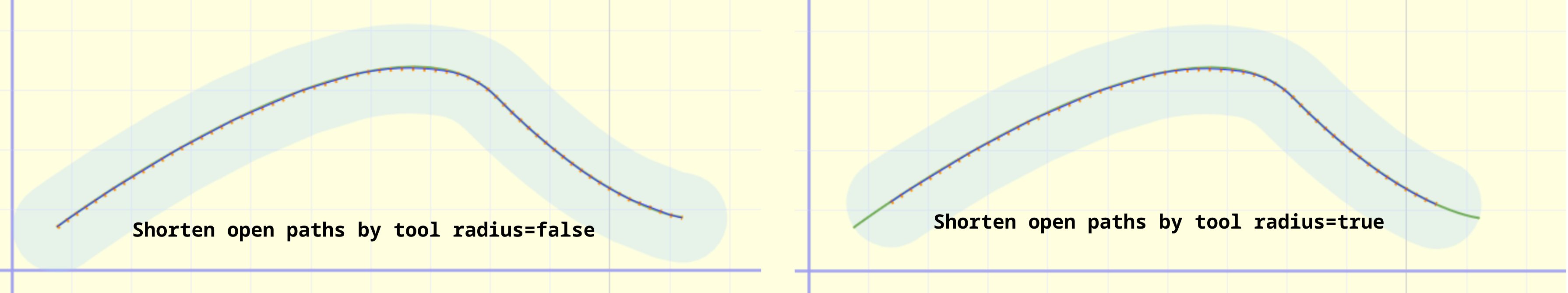
Shorten open paths by tool radius: If you don’t want the cut to extends past the end of open paths due to the tool having a non-zero radius, you can set this to true. See illustration below.
-
Order: Determines processing order. "Level First" will finish one depth for all elements first, before entering next pass. "Depth first" will go all the way down for each element before processing the next.
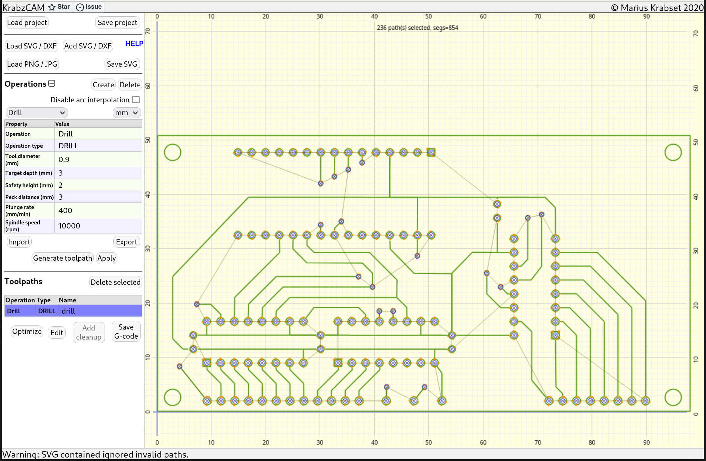
Drill
The operation type DRILL is used for drilling holes. It will calculate a center-point for each selected graphical element (open or closed), and drill a hole at that position. Usually it will make sense to use simple shapes (like circles) for this type of operation.
Properties:
-
Tool diameter: Diameter of the milling tool. For this operation type, this property only affects visualization in the 2D view.
-
Target depth: Determines depth of cut, relative to z-origin. Given as a positive number.
-
Safety height: Determines the z-value during travel. Choose a value high enough to avoid touching the workpiece.
-
Peck distance: For each advancement in this distance, the drill bit will be pulled out and then reenter. Used to clear out chips in the drill hole.
-
Plunge-rate: Determines speed in z-direction during descent into workpiece.
-
Spindle-speed: Determines spindle speed.
Laser
The operation type FOLLOW_PATH_LASER is available for laser engraving tasks. This operation type is similar to FOLLOW_PATH, but is made for use with lasers instead of milling tools.
Properties:
-
Feed-rate: Determines speed in x/y direction during cutting.
-
Laser power: Determines laser power, e.g.. "S-value" in the g-code.
-
Laser ON command: Choose between M3 and M4 as g-code command for turning on the laser. Depends on cnc controller.
Laser raster
The operation type LASERRASTER is used to laser-engrave images.
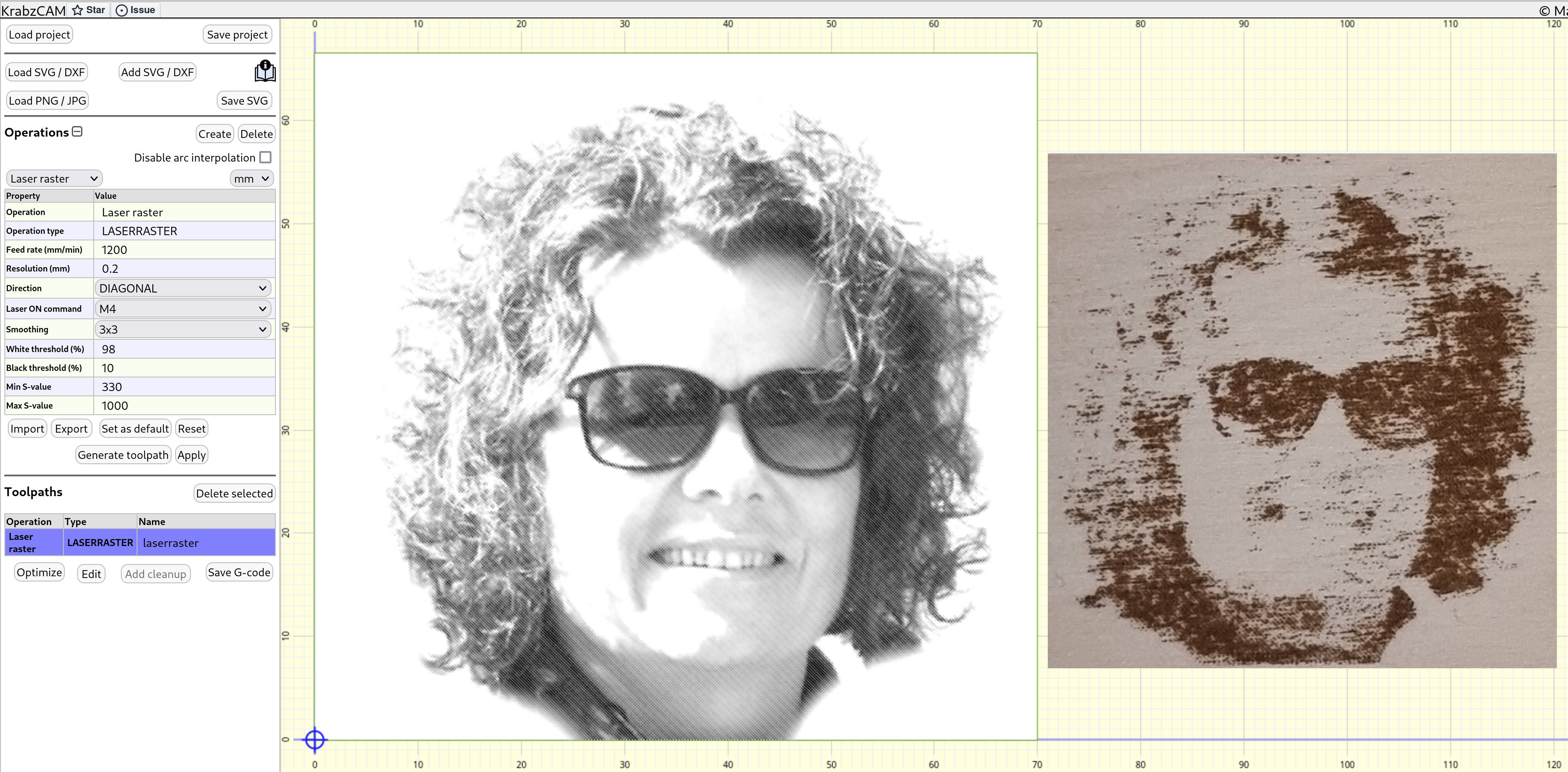
Properties:
-
Feed-rate: Determines speed in x/y direction during engraving.
-
Resolution: Determines output pixel size.
-
Direction: Scan line direction.
-
Laser on command: M3 or M4, depending on cnc firmware. Typically, M4 for Grbl in laser-mode.
-
Smoothing: Optional 3x3 low-pass filter to reduce noise and aliasing.
-
White threshold: Pixels above this value are considered white.
-
Black threshold: Pixels below this value are considered black.
-
Min S-value: Gcode S-value for minimum laser output.
-
Max S-value: Gcode S-value for maximum laser output.
|
Tip
|
It takes a bit of trial-and-error to get these property values tuned correctly. A good ide is to use a test pattern. Lots of those are available on the web. |
Relief rough
The operation type RELIEF_ROUGH is used as a roughing operation for removing excess material before finishing off with a 'relief follow'-operation. Instead of using vector graphics as input, this operation type requires a grayscale image. This image is interpreted as a height-map.
Properties:
-
Tool diameter: Diameter of the milling tool.
-
Roughing clearance: Adds distance to be cleared by the finishing pass.
-
Black depth: Determines depth for black pixel color.
-
White depth: Determines depth for white pixel color.
-
Safety height: Determines the z-value during travel. Choose a value high enough to avoid touching the workpiece.
-
Step down: How much z-distance to advance for each pass.
-
Feed-rate: Determines speed in x/y direction during cutting.
-
Plunge-rate: Determines speed in z-direction during descent into workpiece.
-
Spindle-speed: Determines spindle speed.
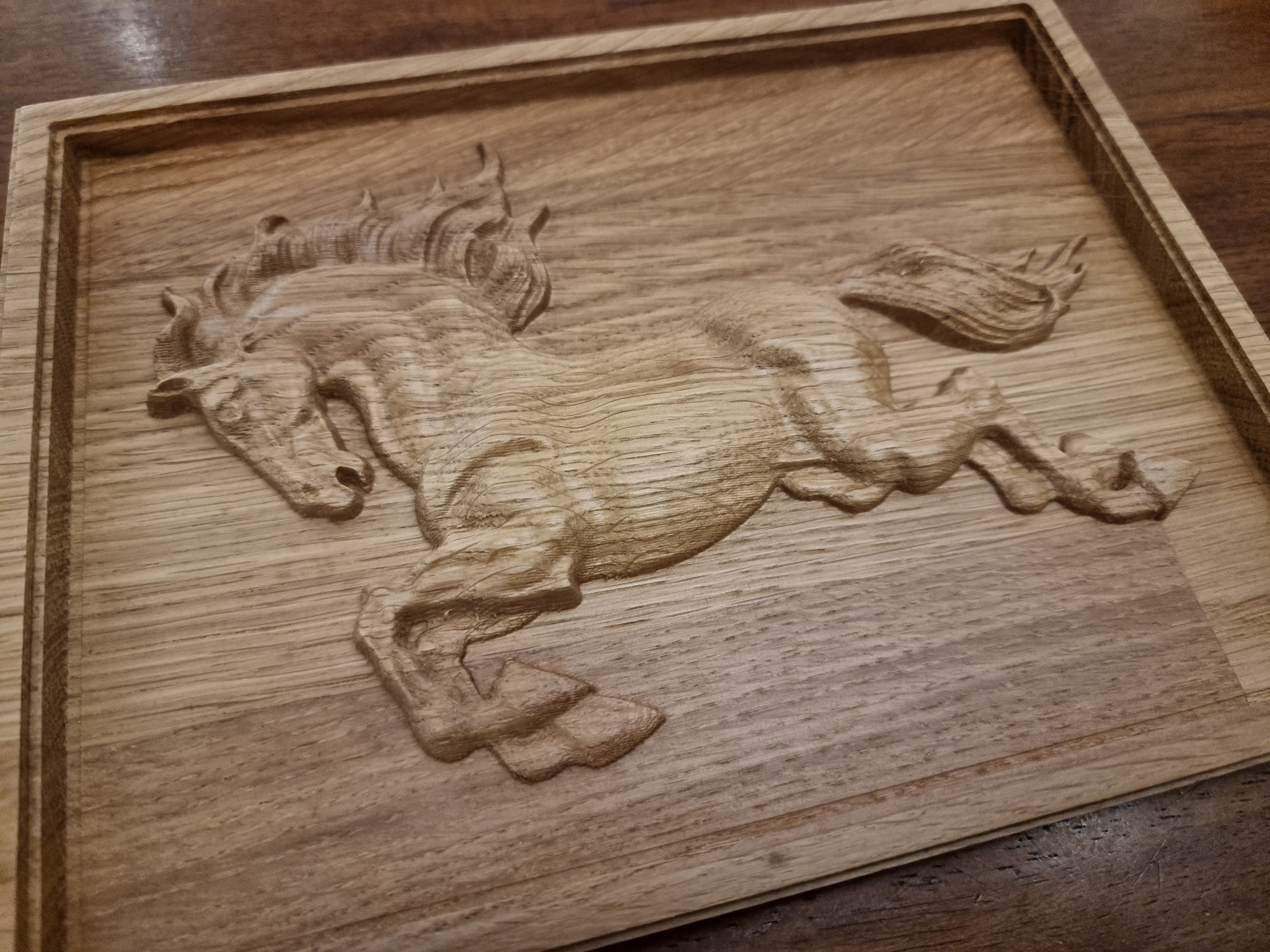
Relief follow
The operation type RELIEF_FOLLOW is used to create reliefs based on grayscale images interpreted as height-maps. Typically, you will first use a RELIEF_ROUGH-operation (see above) to remove most of the material , and then follow with a RELIEF_FOLLOW to carve out the details with a small-diameter tool.
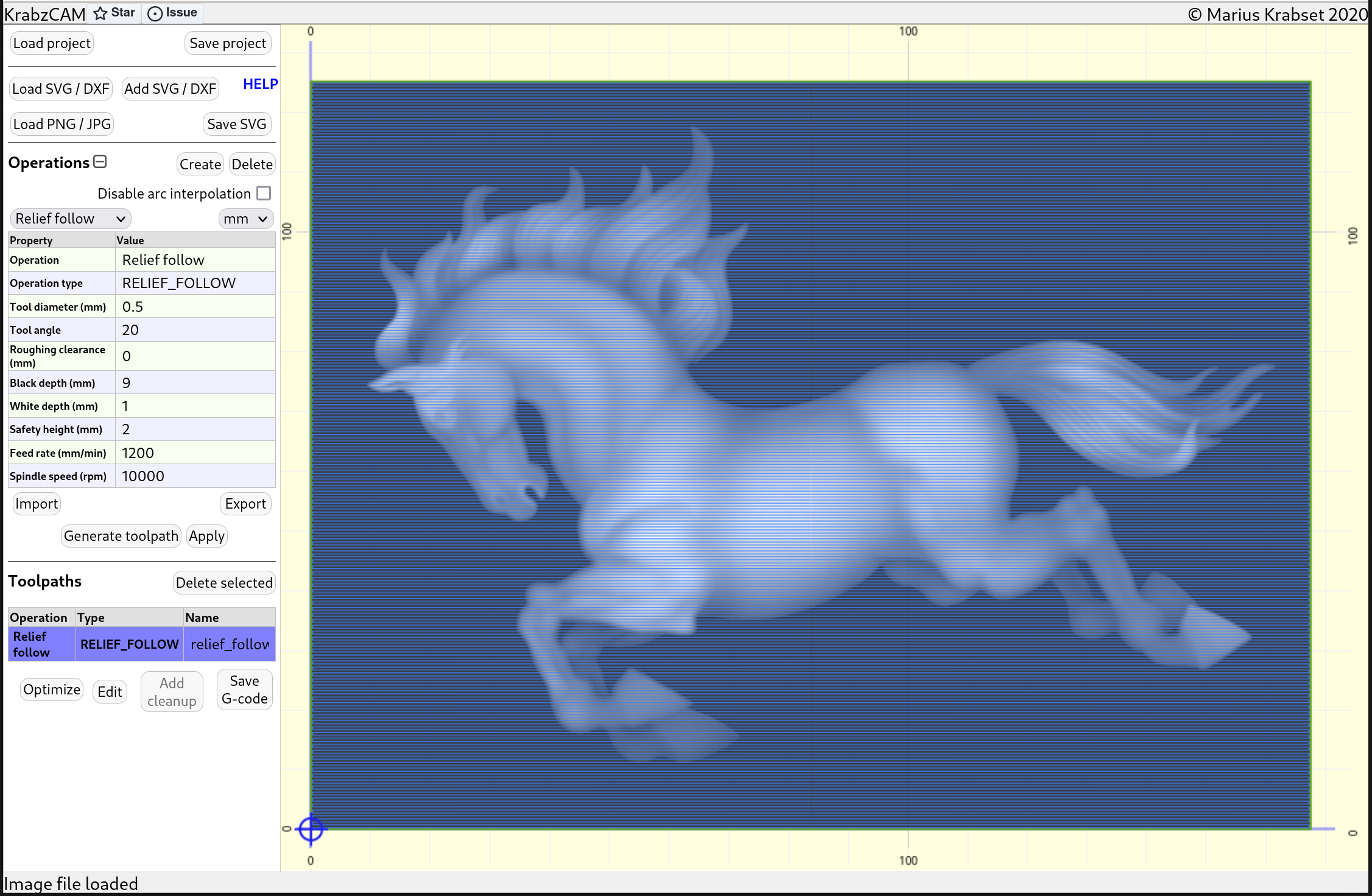
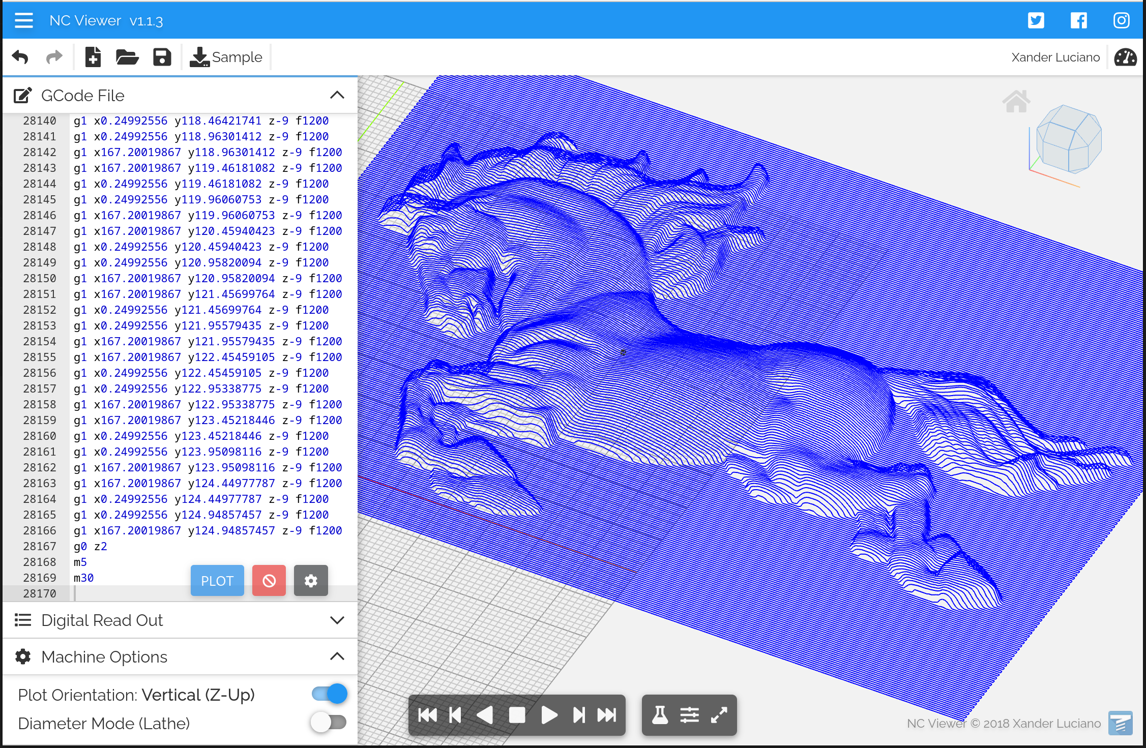
As shown on the above image, RELIEF_FOLLOW operations generate toolpaths running in a horizontal zig-zag pattern.
Properties:
-
Tool diameter: Diameter of the milling tool.
-
Tool angle: It makes sense to use a V-shaped tool for this operation, since you want to combine a small tool diameter for fine details with a v-shape for tool strength. If using a V-shaped tool, set the tool angle with this property. For a straight tool you can use zero. This setting prevents a V-shaped tool from affecting its surroundings when the 'landscape' is steep.
-
Roughing clearance: Adds distance to be cleared by a finishing pass.
-
Black depth: Determines depth for black pixel color.
-
White depth: Determines depth for white pixel color.
-
Safety height: Determines the z-value during travel. Choose a value high enough to avoid touching the workpiece.
-
Step down: How much z-distance to advance for each pass.
-
Feed-rate: Determines speed in x/y direction during cutting.
-
Spindle-speed: Determines spindle speed.
Drag knife
The operation type DRAGKNIFE is used to create drag knife toolpaths. A drag knife is a cutting tool which is typically mounted on a spindle (without enabling the spindle motor!!). It can be used for cutting soft materials like vinyl, creating stickers, cutting/engraving glass etc.
The drag knife rotates freely, and the cutting point is offset from the center of rotation so that it will be dragged behind when we are moving in xy-direction. Whenever the desired cut has a sudden change in direction, the center of rotation needs to be moved to a new location, while the tip of the knife remains stationary. This results in a circular movement called a swivel action. While performing a swivel action, the knife needs to be in contact with the material so the knife only rotates while the tip stays at the same location.
Typically, the knife will be lifted slightly during a swivel, to prevent harm to the material caused by knife rotation. But not too much! The knife still needs to be in contact with the material.
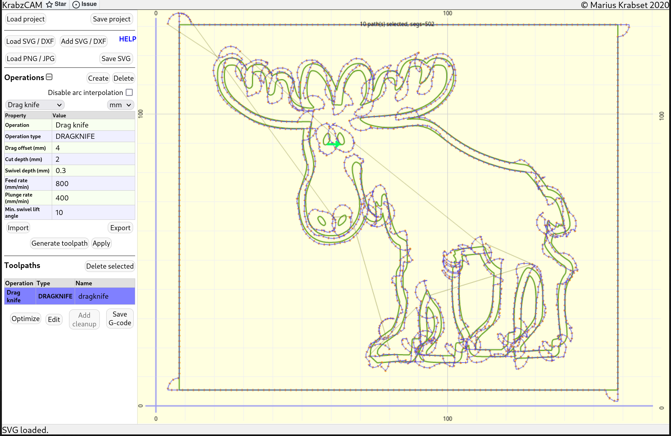
Properties:
-
Drag offset: Distance between the tip of the knife and the center of rotation.
-
Cut depth: How deep to cut
-
Safety height: Determines the z-value during travel. Choose a value high enough to avoid touching the material.
-
Swivel depth: Depth when performing swivel actions. Swiveling is what you do when you prepare for a change in cutting direction. It’s a circular movement around the tip of the knife, without the tip actually moving.
-
Feed-rate: Determines speed in x/y direction during cutting.
-
Plunge-rate: Determines speed in z-direction when moving downwards. (Not really important for this operation)
-
Min swivel lift angle: Minimum angle of direction change for lifting to swivel depth. (So if you only have a slight change in direction, you can just keep on cutting without swiveling)
V-Pocket
The VPOCKET operation type lets you create pockets using a V-bit of a given angle. By using a V-shaped bit you can really create high-detail pockets, since the level of detail can be controlled by the depth of cut.
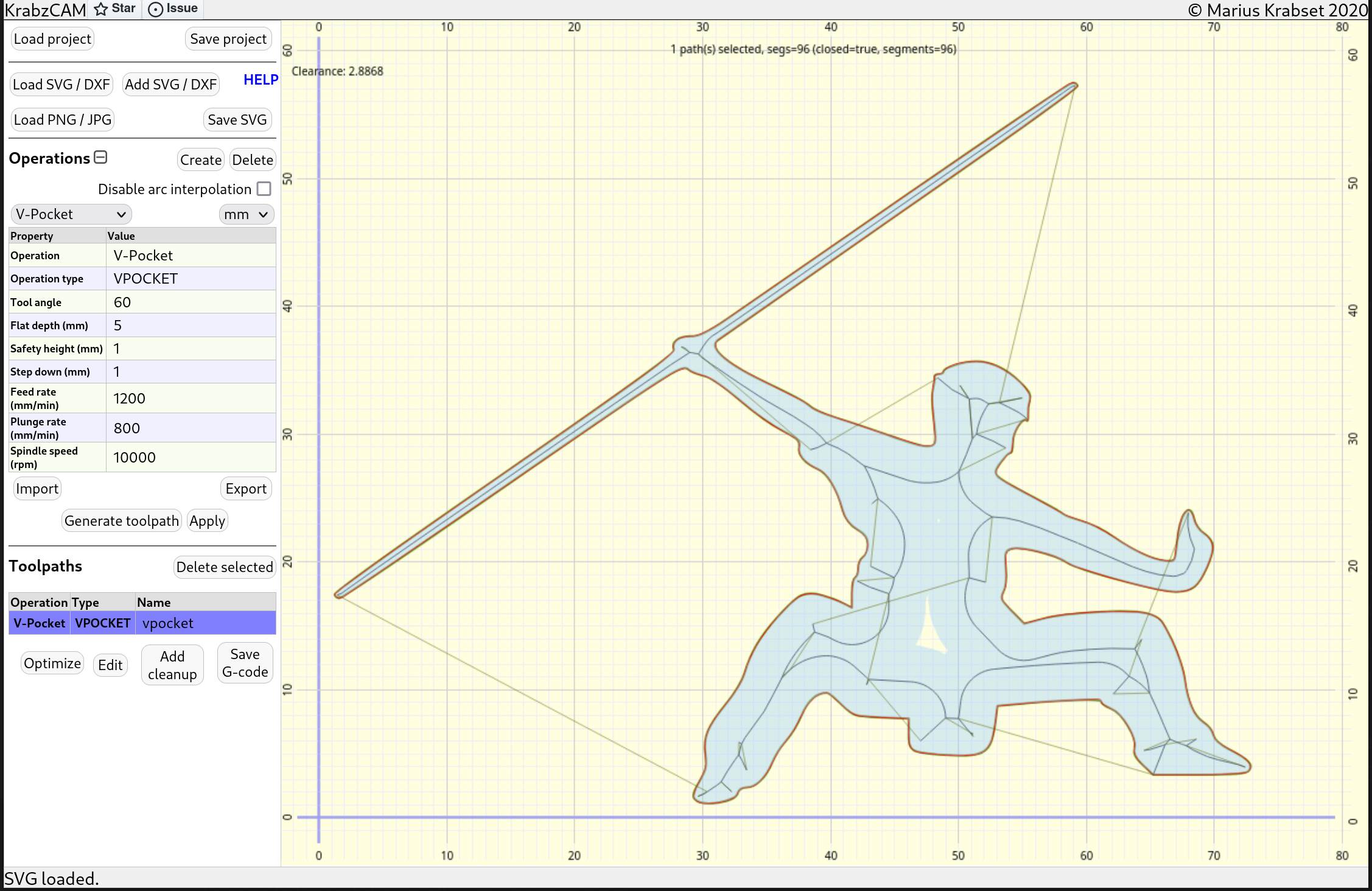
The image above shows a v-pocket toolpath. The area affected by the v-bit is colored light-blue.
Properties:
-
Tool angle: The angle of the V-bit.
-
Flat depth: The maximum depth of cut.
-
Safety height: Determines the z-value during travel.
-
Step down: How much z-distance to advance for each pass.
-
Feed-rate: Determines speed in x/y direction during cutting.
-
Plunge-rate: Determines speed in z-direction when moving downwards.
-
Spindle-speed: Determines spindle speed.
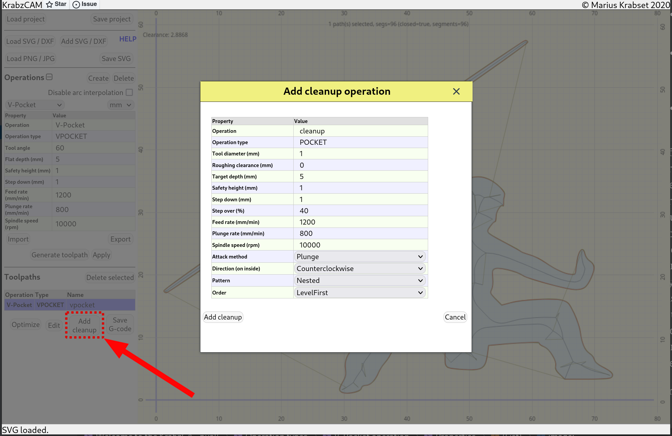
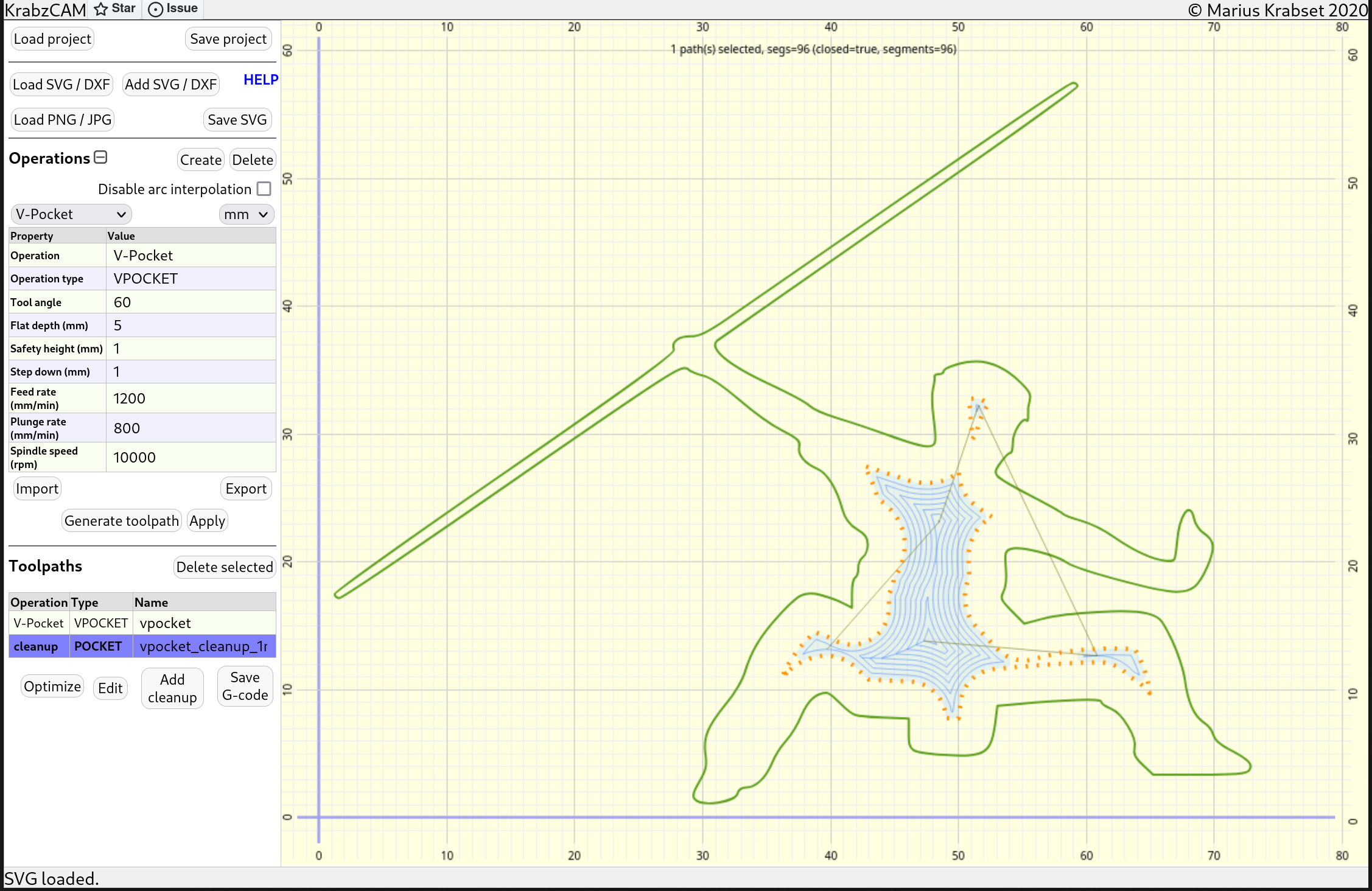
If we look again at the example image above.. Since the flat-depth is set to 5 mm, there is an area in the middle that is unaffected by the cutting tool. This area typically needs to be flattened by a regular endmill pocket operation.
For the VPOCKET and VINLAY (see below) operation-types, this can easily be achieved by using the Add cleanup-button.
This button opens up a dialog for configuring this cleanup-operation.
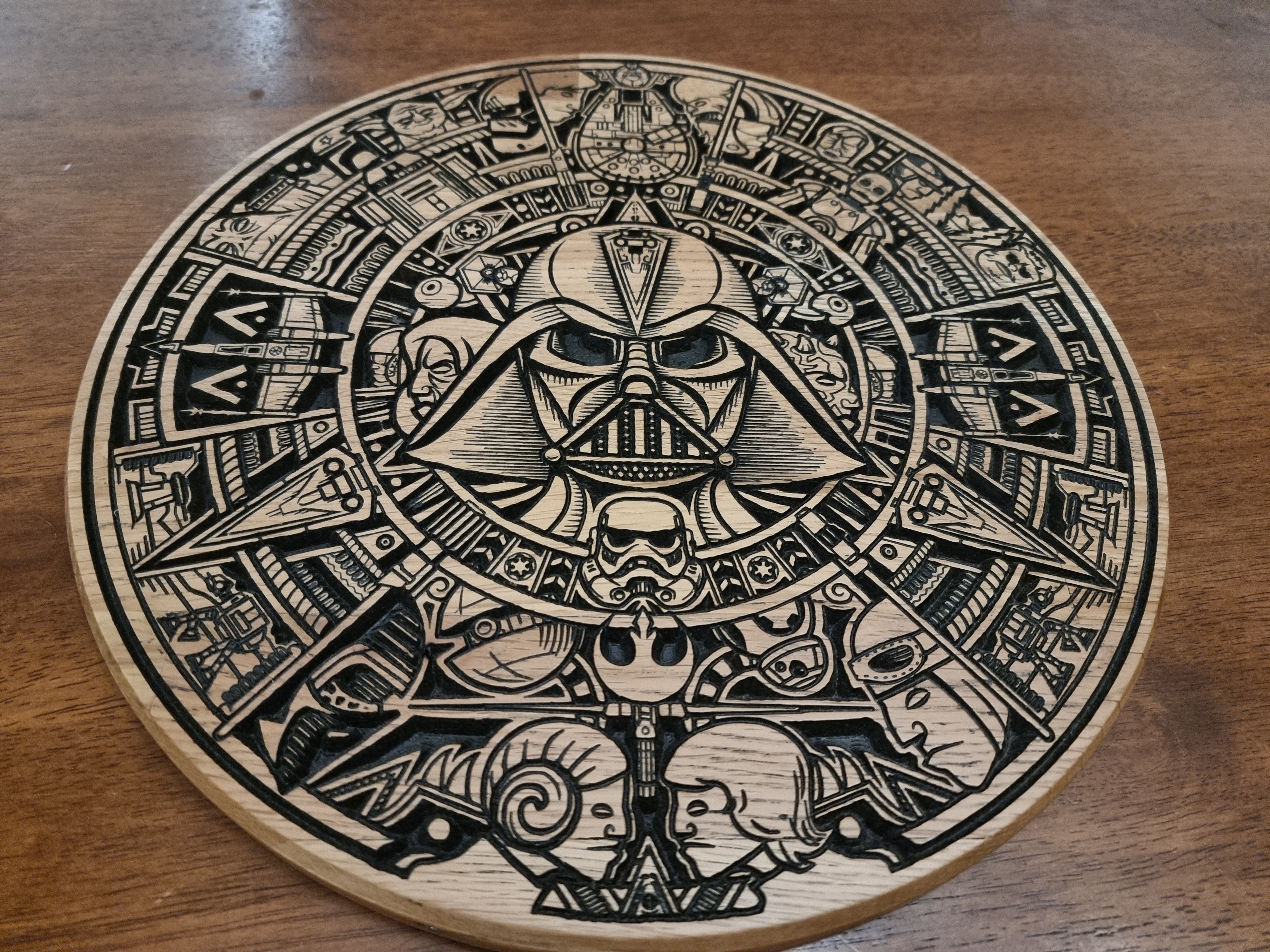
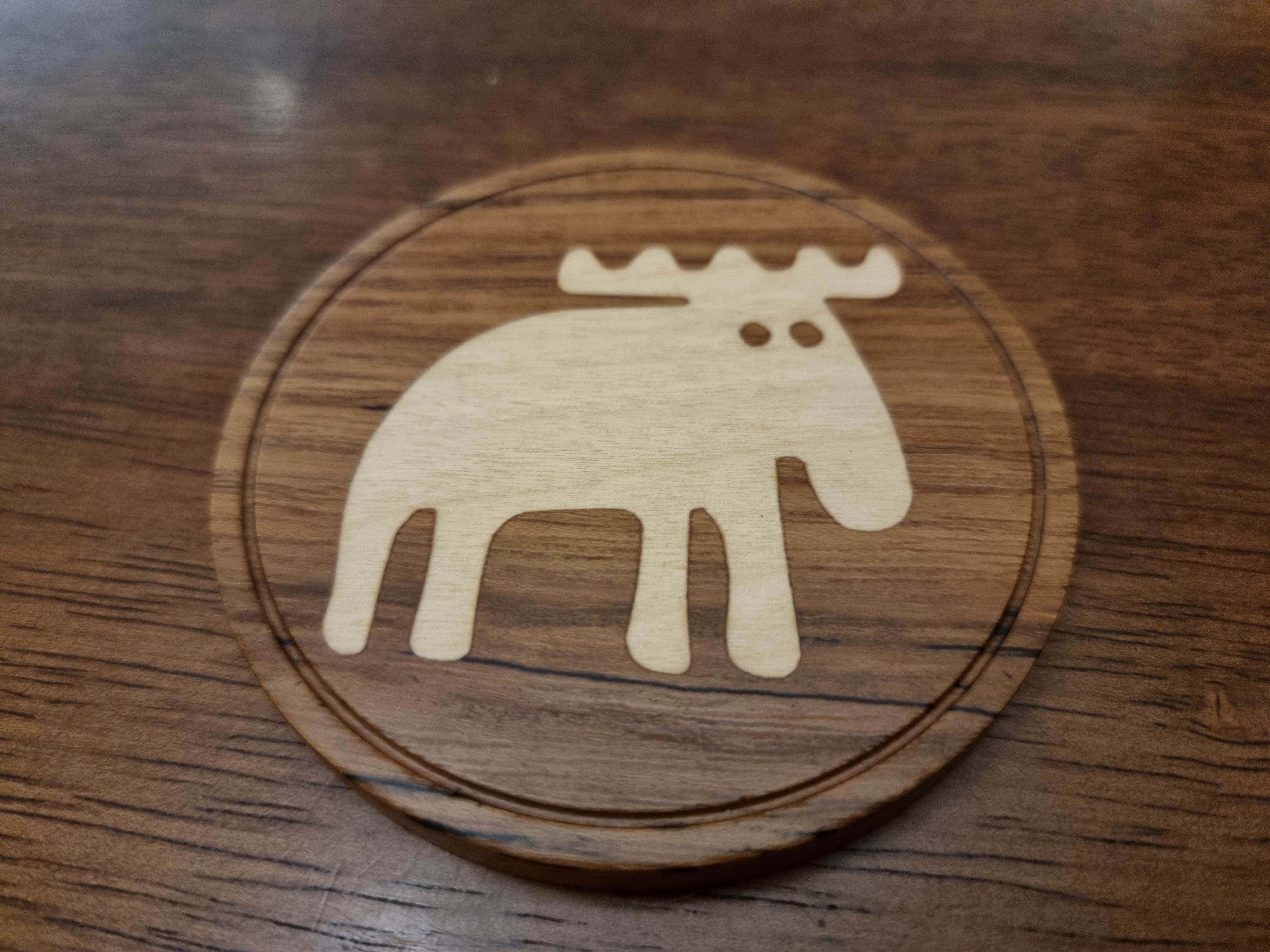
V-Inlay
The VINLAY operation type lets you create 'plugs' for V-bit pockets. Instead of filling the v-pockets with paint (like in the above image), another option is to fill it with a wooden 'plug'(inlay) with another wood tone. This is a technique called 'wooden inlay'.
This is the purpose of the VINLAY operation type.
Properties:
-
Tool angle: The angle of the V-bit.
-
Start depth: V-pocket flat-depth minus glue-gap. (see explanation below)
-
Flat depth: Saw gap. (see explanation below)
-
Safety height: Determines the z-value during travel.
-
Step down: How much z-distance to advance for each pass.
-
Feed-rate: Determines speed in x/y direction during cutting.
-
Plunge-rate: Determines speed in z-direction when moving downwards.
-
Spindle-speed: Determines spindle speed.
-
Flip: Choose between automatic mirroring, or manual. (since plug needs to be mirrored)
-
Create boundary: Choose between automatic or manual boundary around the plug.
-
Boundary clearance : Clearance between artwork and automatic boundary. Determines size of automatically created boundary.
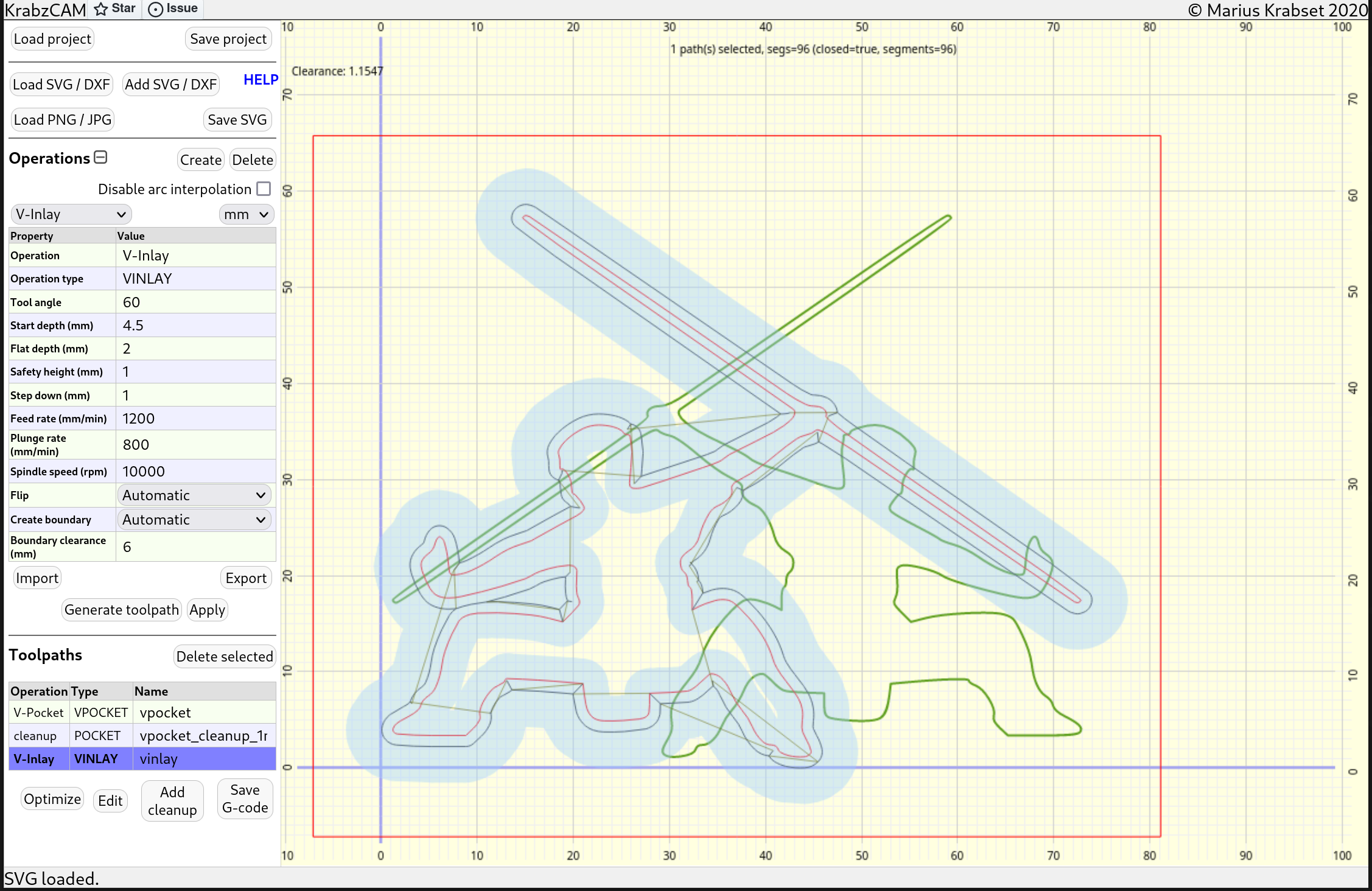
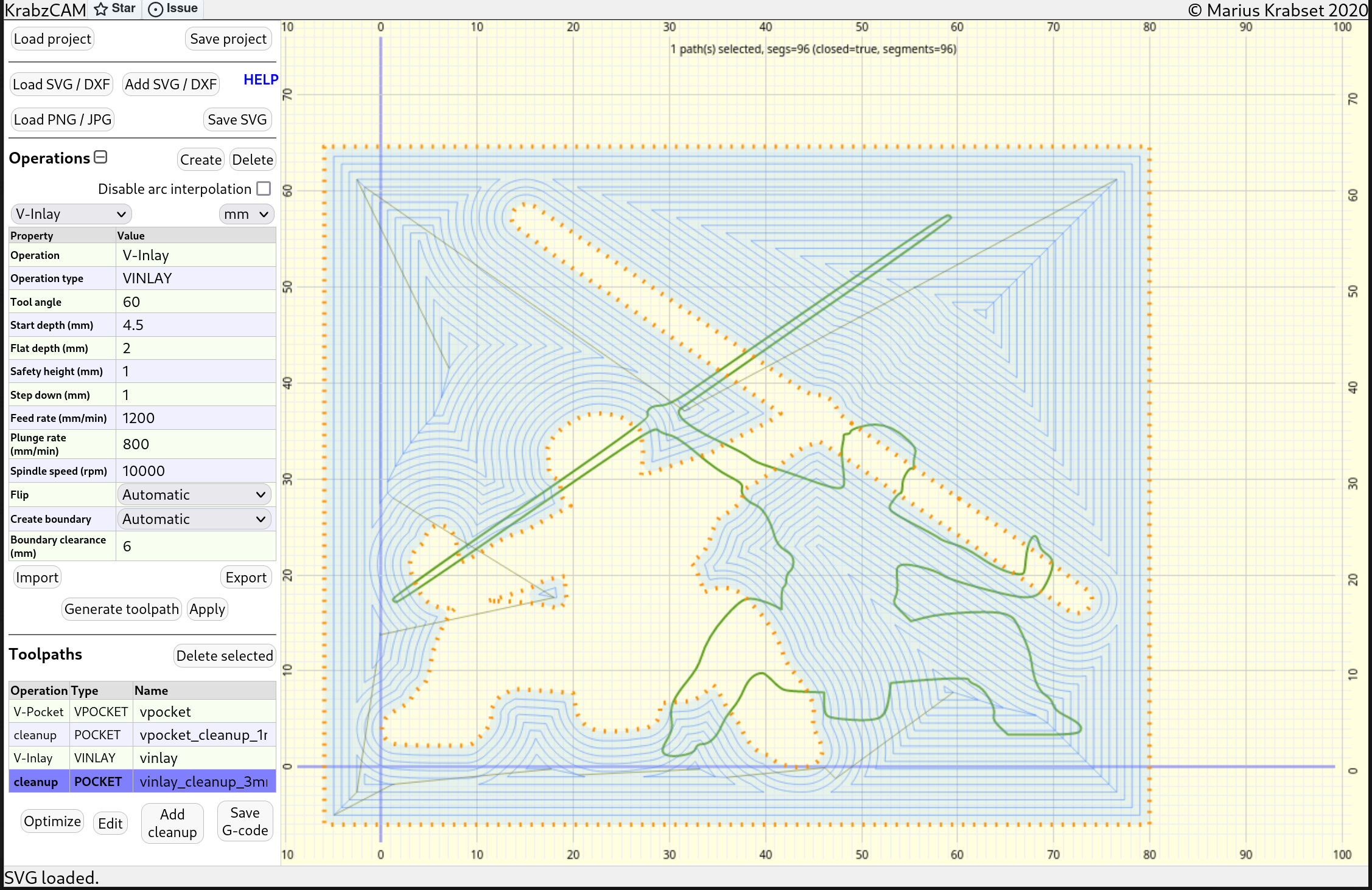
In the example above, all material between the traced toolpath and the boundary (in red) needs to be removed. As the tool-diameter on the tip of a V-bit is zero, this tool is not suitable for this job (it would take forever).
Instead, as shown earlier, we can create a cleanup toolpath using the Add cleanup-button.
Start-depth and Flat-depth
The startDepth and flatDepth properties requires some explanation.

As we see on the image above, for the V-pocket, the flatDepth is simply the maximum depth of cut.
For inlays its a bit more complicated. The startDepth is the distance from the z=zero down to the artwork level (shown with the dotted green line). The artwork-level is the level where the V-bit draws the exact image given by the artwork. When the inlay is inserted into the pocket, their artwork-levels must align.
Since the parts will be glued together, we need a little 'glue-gap'(shown in yellow). So, to calculate the startDepth, we subtract the glue-gap from the flatDepth of the pocket.
Example: If the pocket is 5mm deep(e.g.. flatDepth=5), and we want a 0.5 mm gap for the glue, then the inlay startDepth should be 4.5 mm.
The flatDepth property of the inlay determines the saw gap (shown above). If using a saw to remove the excess part of the inlay (after the glue has dried), the flatDepth should be set close to the thickness of the saw blade, so that it fits in between the parts.

Misc topics
Donate ❤️
I hope you’re finding KrabzCAM useful in your projects. I’ve built and maintained this software as a free tool for the community. If you’ve benefited from using it and would like to show your appreciation, I kindly invite you to consider making a voluntary donation.
Your support helps me dedicate time and resources to maintain, improve, and expand the software — and it means a lot. Even small contributions make a big difference.
bitcoin:BC1QVEDQZQCDYCZ5T5ASX3APAN2N9DDSNRYJDEDWE2
Disclaimer
|
Important
|
This software is free of use. It comes without any warranty. Use it at your own risk. |